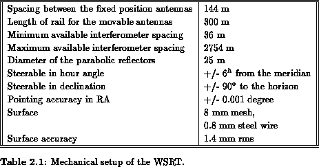
The Westerbork Synthesis Radio Telescope is a radio interferometer with
14 parabolic dishes. The array is built along an accurately measured East-West
line and all interferometer baselines are at right angles to the Earths
rotation axis. Any baseline can therefore be specified by the rectangular
coordinates of the one antenna relative to the other in a plane
perpendicular to the Earth axis. The
and
coordinates are measured in
units of one wavelength at the centre frequency of the observed frequency band
and the
and
directions are fixed in space. At each given point in time
every baseline produces a measurement in the
plane. As the Earth
rotates, every baseline traces an ellipse in this plane.
Since an interferometer has a limited number of telescopes and therefore
a limited number of baselines, the plane is not sampled completely.
Not sampled points are set to zero in order to calculate the Fourier
Transform which gives the radio brightness distribution
over
the field of view, i.e. the region within the main lobe of the antenna
power pattern
.

The shape of the synthesized beam in the coordinate system is
independent of the direction in the sky. In angular direction, however,
the beam is extended in declination by a factor of
. This
is obvious also from the fact that the measured
area is circular
only when viewed from the North celestial pole and becomes elliptical
in the ratio
when seen in projection from other
declinations.
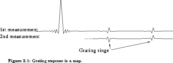
The finite number of measured tracks results in a synthesized pattern,
in which the central maximum is accompanied by a set of concentric grating
circles. Their radii in the
coordinate system are
where
is an integer and
is the regular
interval between the measured tracks in wavelengths. In angular terms
these grating rings are ellipses with semi-axes
and
radians in the right
ascension and declination directions, respectively. The amplitude of the
grating ring is inversely proportional to the square root of its radius. Thus,
to minimize the disturbances caused by the grating rings, the steps
(in wavelengths) between the measured circular tracks in the
plane should be small. Figure 2.1 shows a cross-section of the
synthesized pattern including the first two grating rings. Adding a
second
measurement with the movable antennas shifted by 26 m
will give a regular spacing of 36 m between the circles in the
plane.
This corresponds to grating rings with twice the previous radii, i.e. all
the odd-numbered rings have been eliminated. After 2, 4, etc.
measurements with suitable positions of the movable antennas, the
remaining grating rings will be 2, 4, etc. times as in the original set
of rings. A general treatment of grating rings is given
by Bracewell and Thompson (1973).


Since 1990 the WSRT can work in a new observing mode, using the mosaicing technique. Recent on-line and off-line software development by R. Braun, H. van Someren-Gréve and W. Brouw has made this mosaicing concept possible and allows us to make this mosaicing concept more understandable in terms of theoretical knowledge and software implementation. Because of these developments it allows us to make this survey possible. This is the only way at this moment to observe large areas of sky in one 12 hour observation.